How to Select and Maintain Industrial Drive Shafts: An Engineer's Guide
Key Takeaways
- A drive shaft transmits torque and rotation; correct selection starts with torque and RPM ratings.
- Length, operating angle, and universal joint type all affect load capacity and service life.
- Vibration, wear, and imbalance are the primary failure modes that must be monitored.
- A preventive maintenance plan and inspection schedule catch problems before catastrophic failure.
- The repair-or-replace decision depends on the severity of wear, misalignment, and the cost of downtime.
How to Select and Maintain Drive Shafts Like a Professional
In our previous article, we covered the overview of industrial drive shafts and their importance in power transmission. This guide dives into what maintenance engineers face every day: how to select the right drive shaft and how to maintain it for durability. Because choosing wrong or maintaining poorly results in the most expensive downtime a plant can incur.
1. Principles for Selecting the Right Drive Shaft
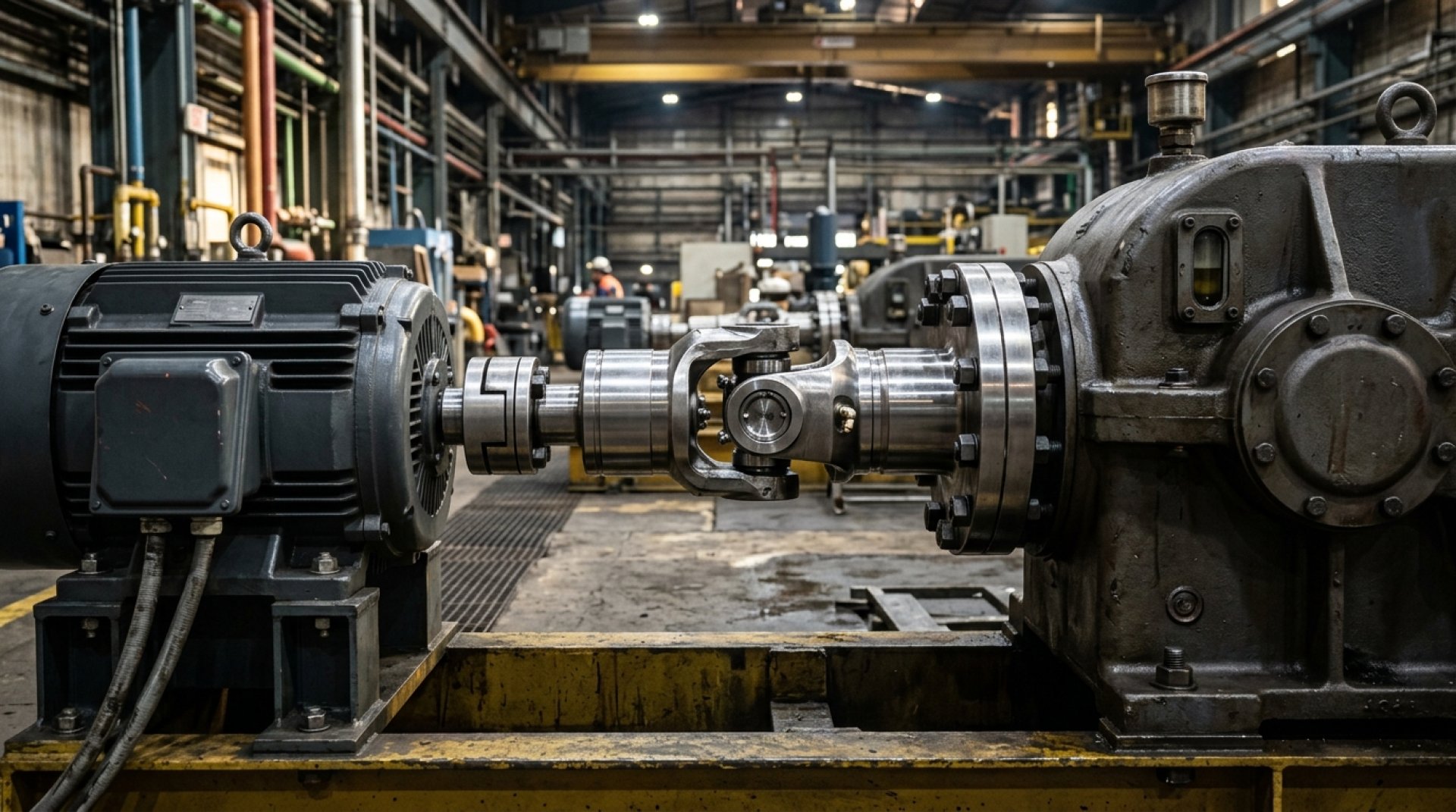
A drive shaft is a power-transmission component that must be selected by careful engineering values, not merely by getting the length right. The main factors to consider are:
- Torque: The shaft must handle the maximum torque the system can produce, including peak (shock) torque at startup, always with a safety factor. Undersizing here is a common cause of fatigue cracking, while reversing or pulsating loads call for an even larger margin than steady-state duty.
- RPM: Every shaft has a critical speed at which it resonates; operating near or beyond it causes severe vibration that can wreck the shaft and its bearings. Greater length lowers the critical speed, so a long, slender shaft may need to run well below the RPM a short, stiff one could handle, or be split into sections.
- Length and Operating Angle: Very long shafts may require a center bearing to stay below critical speed, and the working angles of the universal joints at both ends should be equal so they cancel out the non-uniform angular velocity each joint introduces. Unequal angles cause a twice-per-revolution speed fluctuation that drives vibration and joint wear.
- Universal Joint Type: U-joints accommodate angular misalignment, while flexible couplings handle small parallel offsets; match the joint to the equipment's motion. Where both angular and axial movement occur, a slip-yoke or double-cardan arrangement lets the shaft change length and angle without binding.
Another often-overlooked factor is material and environment. Carbon steel shafts suit general duty, but in high-humidity or chemical-laden applications, stainless steel or corrosion-resistant composite materials should be chosen. Selecting the wrong material from the outset will cause the shaft to degrade quickly no matter how well it is maintained.
2. Alignment is Everything
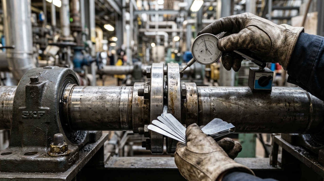
Even with the right shaft selected, installing it with misalignment forces the shaft to flex and bend with every revolution. Engineers should use laser alignment tools rather than straightedges or eyeballing. Proper alignment dramatically reduces the load on bearings and joints and is the most cost-effective preventive investment available.
There are two main forms of misalignment that must both be corrected: parallel (offset) misalignment, where the two axes are parallel but not in the same line, and angular misalignment, where the axes meet at an angle. Complete alignment corrects both simultaneously, and it should ideally be performed at the machine's actual operating temperature, because thermal growth can shift the alignment values measured on a cold machine.
3. Primary Failure Modes
Engineers should watch for these warning signs:
- Vibration: Usually caused by misalignment or imbalance; if left unchecked it spreads to destroy bearings and the machine base.
- Imbalance: Caused by uneven wear, accumulated debris, a lost balance weight, or a bent shaft, producing a centrifugal force that grows with the square of the rotational speed, so even a small unbalance becomes destructive at high RPM. Dynamic balancing on a balancing machine restores smooth running.
- Joint and Coupling Wear: Worn U-joint needle bearings or coupling elements develop backlash, leading to jerky power transmission, a noticeable clunk on load reversal, and noise. Left unaddressed, the play accelerates and can shear the joint entirely.
- Corrosion and Fatigue: Especially in humid environments such as cooling tower fans, where the shaft must constantly withstand moisture and chemicals.
4. Preventive Maintenance Plan and Inspection Schedule
Good maintenance should be systematic and scheduled:
- Weekly: Listen for abnormal noise, feel for vibration by hand, and check for grease leaks or thrown grease around the joints, which signals a failing seal.
- Monthly: Lubricate at grease points until fresh grease purges, verify flange bolt torque against spec, and inspect joint condition for play by trying to twist the shaft by hand with the drive locked out.
- Quarterly/Annually: Measure vibration with instruments (vibration analysis) and trend the readings over time to catch gradual deterioration, verify alignment with a laser tool, inspect for surface cracks or corrosion, and re-balance when necessary.
5. Repair or Replace?
When damage is found, the question is whether to repair or replace. If the wear is in a joint or coupling that can be swapped individually, repair is usually more economical. But if the shaft itself shows fatigue, cracks, permanent bending, or severe corrosion, replacement is safer and more cost-effective long-term, because a weakened shaft risks sudden failure that halts the entire production line.
A key piece of advice: do not decide on the price of the part alone, but calculate the "total cost of downtime." If a shaft sits at a critical point in the production line, replacing it preventively before it fails mid-run is often far cheaper than waiting for it to break and forcing an emergency stop. Keeping a spare on hand for shafts at critical points is therefore a worthwhile strategy. Innovek is ready to advise on the selection, alignment, and maintenance planning of drive shafts and related power-transmission equipment, elevating the reliability and reducing the downtime of your machinery.